|
INSTALLATION INSTRUCTIONS FOR CONTOUR/MONDEO 2.0l ALUMINUM INTAKE KIT Gjengitt med tillatelse fra CTA Automotive Consulting/Reproduced by written permission from CTA Automotive Consulting
The following
instructions are a guide to help you install your new Intake.
Some basic tools will be required to do this job; these
are screwdrivers, a pair of pliers, vice grips (locking
pliers) and a socket set.
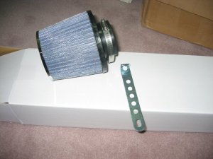
First you will
need to inspect that all the parts that came with the kit
and that shipping did not damage anything, also this way
you will become more familiar with the parts that you are
about to install. To do this, you will not need an engineer’s
degree, as long as you don’t rush the job and enjoy
what you are doing.
Note the term, Air temperature
sensor is going to be mention a few times. This is only
regarding mid 99 and older vehicles. From 99’s and up, the sensor is built in into the MAF. |
|
Open main fuse box and remove fuses 4 and 11 (up to mid 99) or fuse 6 for late 99 and newer vehicles. The main fuse box is located beside the battery. This will reset the computer so that it will learn the new parameters after the installation is completed.
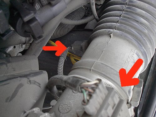
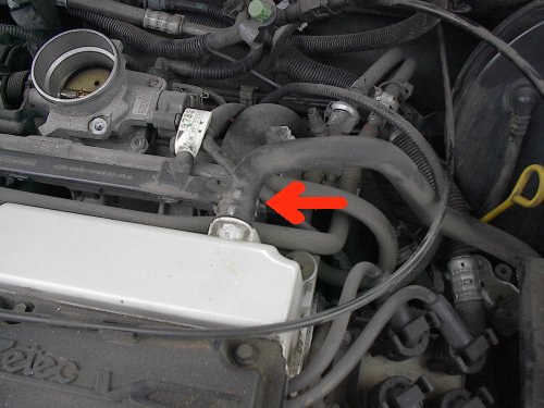
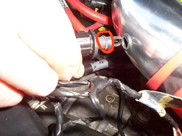
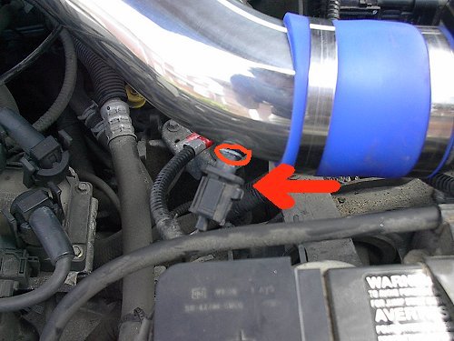
Unplug the MAF and the air temperature
sensor electrical connectors as shown in Figure 1 (1998 Vehicle
shown). NOTE: The IAT is a screw in type 97 and older vehicles. |
FIGURE 1 |
|
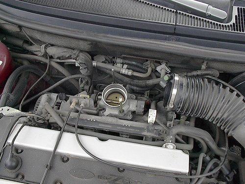
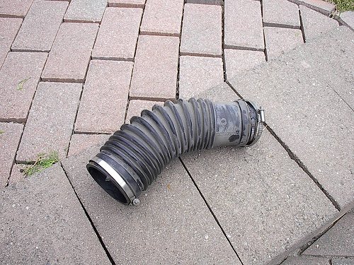
Remove the resonator and stock intake tube as shown in Figure 2. If you have not already done so, remove the IAT from the intake tube, if so equipped (Figure 2.1). For pre 98 vehicles, unscrew the IAT from the intake tube. Using a pair of vice grips (locking pliers), remove the intake resonator hold down studs. These may be very tight and penetrating lubricant may need to be sprayed to assist in loosening the studs.
|
FIGURE 2
FIGURE 2.1 |
|
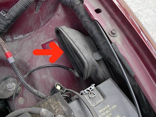
Remove
fender boot as shown in Figure 3. You may choose to remove the
remaining plastic fender inlet assembly.
|
FIGURE 3 |
|
All model year vehicles: Do not remove crankcase breather hose. Disconnect the end of the hose that was attached to the stock intake tube. (Figure 4)
|
FIGURE 4 |
|
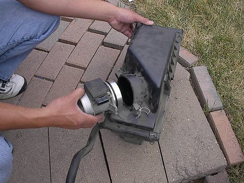
Remove MAF from the stock air box by releasing holding clamps, if so equipped. (Figure 5) |
FIGURE 5 |
|
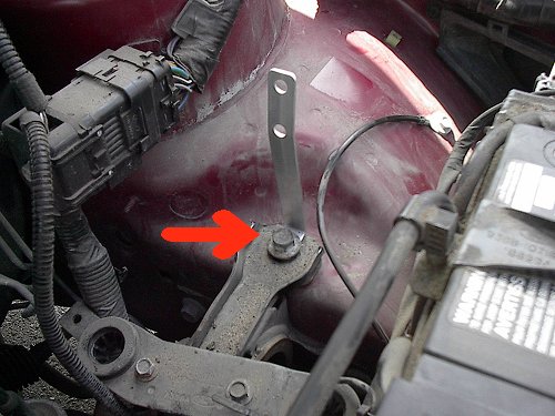
Install
the supplied aluminum bracket near the driver's side fender.
|
FIGURE 6
FIGURE 6A
FIGURE 6B |
|
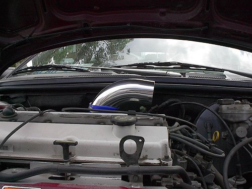
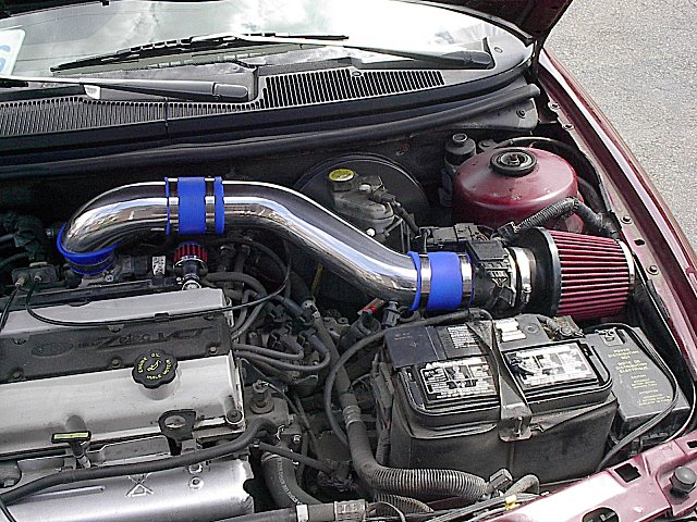
Install
throttle body elbow and coupling assembly using the supplied
clamps. Please note
the angle of the elbow. If not installed in this manner, the
elbow may touch the hood.
|
FIGURE 7 |
|
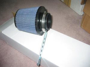
Install supplied air filter to the inlet side of the MAF. Please note the orientation of the MAF as it has a specific inlet and outlet. The filter may require some stretching to fit over the MAF. Please note that this
may be a bit difficult but will
fit as shown in Figure 8. |
FIGURE 8 |
|
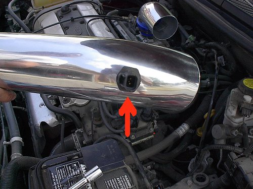
98
to 99 vehicles:
Pre 98 vehicles (Not shown): Carefully, using the correct size wrench, thread the IAT into the hole provided. View from inside the intake tube, that there is no gaps and that the orientation of the IAT is correct. The sensing tip should be in the air stream with the plastic supports in the vertical position.
|
FIGURE 9
FIGURE 9.1 |
|
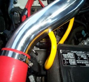
Assemble the remaining portion of the intake kit. 1. Attach a coupling to the throttle body elbow then insert the main intake tube. Secure using the supplied clamps but do not completely tighten. 2. Attach the remaining coupling and then the MAF using the supplied clamps. 3. Attach the MAF to the previously installed MAF support bracket. The support bracket may need to be slightly bent to accommodate the fitment in your vehicle. Snug all connections. Do not tighten completely until proper fitment has been established. 4. All model year vehicles: Insert the silicone hose, provided with the kit, into the existing hose that was removed from the stock intake tube (Figure 4). Then cut hose to length, and insert other end onto the port on the new intake tube (Figure 10.1). Please use the zip ties provided, if necessary, to secure the ends of the new hose.
5. Once proper fitment has been
established, secure and tighten all clamps and fasteners.
|
FIGURE 10
FIGURE 10.1 |
|
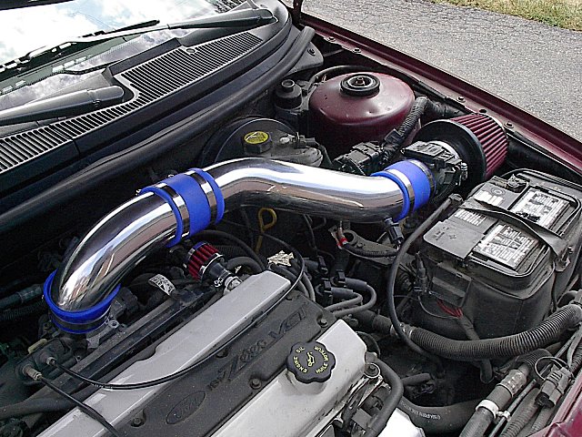
Reinstall IAT and MAF electrical connectors.
|
FIGURE 11 |
|
|
|
|
|
|
|
|